Posted
on 28 Dec 2023, 10:21 am,
by admin,
under Uncategorized.
During the really cold weather in early December 2023, the relative humidity in my loft was 100% and condensation was literally dripping from the roofing felt onto the loft insulation and onto the odds and ends I have stored up there.
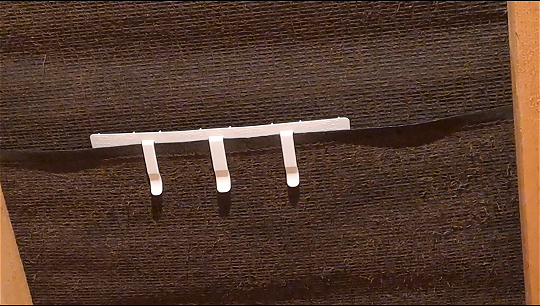
I wondered about improving the soffit ventilation but a local roofing firm said it seemed fine and suggested that I fit some felt-lap vents. I’d never heard of them before but I ordered some from Amazon and they arrived next day.
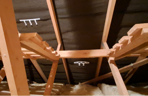
Videos on YouTube recommend fitting some close to loft “floor” (just above the insulation) and some close to the top, near the ridge tiles. The videos recommend scattering them randomly rather than fitting them in straight lines facing each other so as to create a bit of turbulance and avoid air just entering via one vent and leaving by the one closest. I ended up fitting 20 throughout the loft. I ordered 10 each of slightly different designs in case one works better than the other.
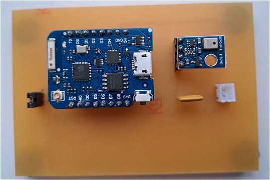
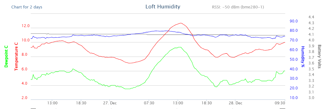
I’ve fitted one of my hobby project temperature/humidity transmitters up there so I can monitor the humidity. Although the temperature has been relatively high the last week or two, the humidity seems to be holding better at around 78 – 80%. Without the vents, the humidity was more-or-less stuck at 100% regardless of the temperature. It has been quite windy too which probably helps so time will tell if the felt-lap vents have improved things.
Posted
on 30 Mar 2023, 11:04 am,
by admin,
under Uncategorized.
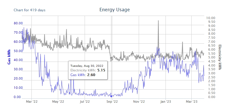
Towards the end of August 2022, I tested the standby power consumption of the majority of my home electrical items and was able to reduce my daily energy consumption from around 6.5kWh to nearer 5kWh by switching off or unplugging items instead of leaving them on standby. The grey plot in the chart below shows the drop on August 30th.
The Freesat PVR was the worse culprit – taking 7 W for the box itself plus another 5 W to power the dish/LNB – a total of 12 Watts whilst on standby. Some items, such as the fridge and the Freeview PVR need to stay running 24 hours a day but the rest were switched off until required.
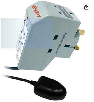
I was able to power down the TV automatically using an E-on power-down plug which, unfortunately seems to be no longer available.
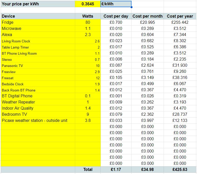
Thanks to a friend who understands spreadsheets better than I do, I was able to list the electrical items and work out the annual cost.
I’ve just updated the spreadsheet to include the current electrical unit rate (36.45p/kWh) :
Leaving all those items on standby would have cost a massive £425.63 a year.
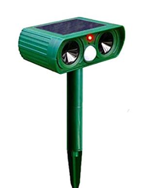
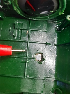
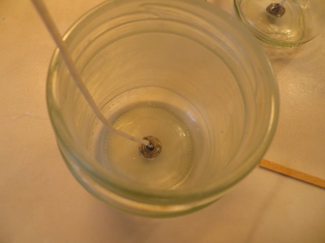
A couple of years ago, I bought two of these fox deterrents for my front lawn but they stopped working during the winter. I’d assumed that there just wasn’t enough sun to keep the internal batteries charged but, when I took a closer look this week, I discovered they both have a manufacturing fault.
The solder joint on the positive wire from the solar panel had given way – in fact it had never been soldered properly at all. The wire was held in place by little more than hot-melt glue. The connection on the solar panel itself seems to have some sort of nickel-plating and refused all attempts to take solder to reconnect the wire properly.
Normally, connections to this type of metal are made using a cold welding process but the blob of solder on the wire showed the manufacturer had tried to use ordinary tin/lead or lead free solder
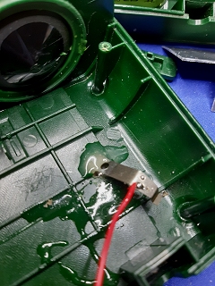
I was able to make a quick and dirty repair by cleaning off the hot-melt glue from around the connection and slipping a piece of thin metal between the top of the enclosure and the underside of the solar panel. I’ve hopefully held it in place with a blob of Araldite.
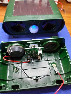
The third photo below shows one unit now charging away (as shown by the blue LED) and the second unit just waiting for the Araldite to harden before reassembling it.
You may also have spotted in the bottom photo that, although the exterior of the units give the impression they have two ultrasonic sounders, one is just a dummy and they do, in fact, only have one!
A friend recently sent me a link to this little gem of a transceiver on eBay. Although it’s been around for quite some time, it was new to me and, for the amazingly low price of £19, it was too good to miss. When you consider that the established manufacturers of amateur radio equipment would be asking anything from around £150 to £200 for a similar dual-bander, I wasn’t expecting much.
But I was wrong! It looks and feels every bit as good as its expensive counterparts. Apparently, the audio quality is good – although I haven’t tested it myself yet – but it is a bit tricky to set up with your favourite 2m and 70cm amateur band channels. Like everything, though, once you get the hang of it, it’s quite straightforward.
For my own reference as much as anyone else’s, here’s a quick cheat sheet: Programming the Baofeng UV-5R Radio
Common ("Global") Settings:
These settings can be set on a "per-channel" basis in Memory Channel mode but the last settings will persist across Simplex Channels and Frequency Mode. The repeater offset setting (#26) may be left at the last setting provided that the Repeater Shift Direction (#25) is set to OFF.
(a) MENU -> #13 for Transmit CTCSS. MENU-> CTCSS frequency (eg: 110.9Hz). MENU to confirm
(b) #25 for repeater shift direction: -, + or OFF. MENU to confirm. (- for 2m. + for 70cms).
(c) #26 for repeater offset: 000.600 for 2m or 001.600 for 70cms or OFF for Simplex. MENU to confirm.
(d) #27 to select a memory channel to program. MENU -> #27. MENU to confirm.
(e) EXIT.
Repeater channels:
You can get a list of repeater settings (INPUT and OUTPUT frequencies, CTCSS frequency, Offset frequency and Shift Direction) here: ukrepeater.net.
There's no point programming the Repeater Offset or the Repeater Offset Direction because both Input and Output repeater frequencies are saved in the memory channel anyway.
(a) VFO/MR -- set to Frequency mode and type in repeater OUTPUT frequency (Our radio's RX frequency).
(b) Press MENU -> #13 -> MENU. Select CTCSS frequency (eg: 110.9Hz). MENU to confirm.
(c) #27 for memory channel -> MENU -> type channel number. -> MENU to confirm.
(d) EXIT
(e) Check still in Frequency mode. (VFO/MR).
(f) Type the repeater INPUT frequency (Our radio's TX frequency).
(g) MENU -> #27 -> MENU -> Select same memory channel as (e) -> MENU to confirm. EXIT.
Simplex Channels:
(a) MENU -> #13 -> MENU -> OFF (Transmit CTCSS to OFF) -> MENU. EXIT.
(b) MENU -> #25 -> MENU -> OFF (Repeater Shift Direction to OFF) -> MENU. EXIT.
(c) VFO/MR -- set to Frequency mode and type simplex frequency.
(d) MENU -> #27 -> MENU. Type Channel Number. MENU. EXIT.
(e) Still in Frequency mode so -> Type next simplex frequency (or use up/down arrows).
(f) MENU -> {* #27 ->} MENU. Type Channel Number (or use up/down arrows). MENU. EXIT.
(g) Repeat (e) and (f) to store other frequencies in memory channels.
* Menu is still in Memory Channel Number sub-menu so no need to type #27 after first time.
Posted
on 14 Mar 2016, 11:56 am,
by admin,
under Car, Electronics.
In July last year, I posted about a dashcam I’d fitted to the car.. well, the GPS unit packed up last week. Also, the connections on the mounting bracket (which were always a bit suspect) had got worse so I decided it was time for a new dashcam.
Unfortunately, of necessity, these cameras operate in what must be one of the worst environments possible for a bit of domestic electronics – stuck at the top of the windscreen in the full glare and heat of the sun (if we’re lucky) so I guess 18 months is a reasonable time for them to last – especially for low to mid-priced units such as the E-Prance 0803.
So, I ordered one of these. I don’t know if mine was faulty but the GPS unit wasn’t working and it wouldn’t remember any of the settings I’d configured. So, back it went for a full refund.
I’ve now ordered the latest version of the E-Prance camera – the 0806. So far, it seems to be working as expected (although it’s not fitted in the car as yet).
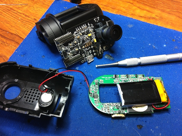
I thought it would be interesting (to me anyway) to open up the old E-Prance 0803 because I wanted to disconnect the defunct GPS unit internally and I wanted to see what exactly was used as the standby power supply. From the very short time the standby supply lasted, my guess was that it used a super-capacitor.
Click the pics for a larger version.
I was surprised to find that it uses a fairly large lithium-polymer battery rated at 400mAh. Presumably it was another victim of the excessively high temperature inside the unit as it didn’t really hold any meaningful charge at all.
Other than that, I was actually quite impressed at the overall quality of the camera’s construction. Two double-sided PCBs mated with three high-quality miniature two-row header plugs and sockets.
The latest model has addressed the overheating issue (basically by drilling loads of holes in the case) so, hopefully, it will last at least as long as the old one.
The old one is now re-assembled (and working!) so I intend to install it in the rear windscreen to see if it will deter the bane of my life – tailgaters!